2011_P14
Controlul semafoarelor intr-o intersectie
Descriere
Tema proiectului este Controlul semafoarelor intr-o intersectie printr-un circuit implementat fizic pe o placa de test.
Intersectia pe care dorim s-o controlam este formata din 2 strazi, fiecare cu 2 sensuri de mers (in total avem 4 semafoare). Fiecare semafor are 2 culori: rosu, semnifica accesul interzis in intersectie, si verde, semnifica accesul liber in intersectie.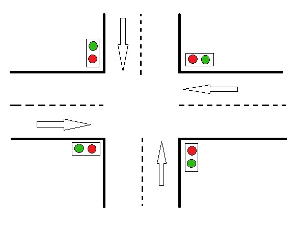
Project Requirements
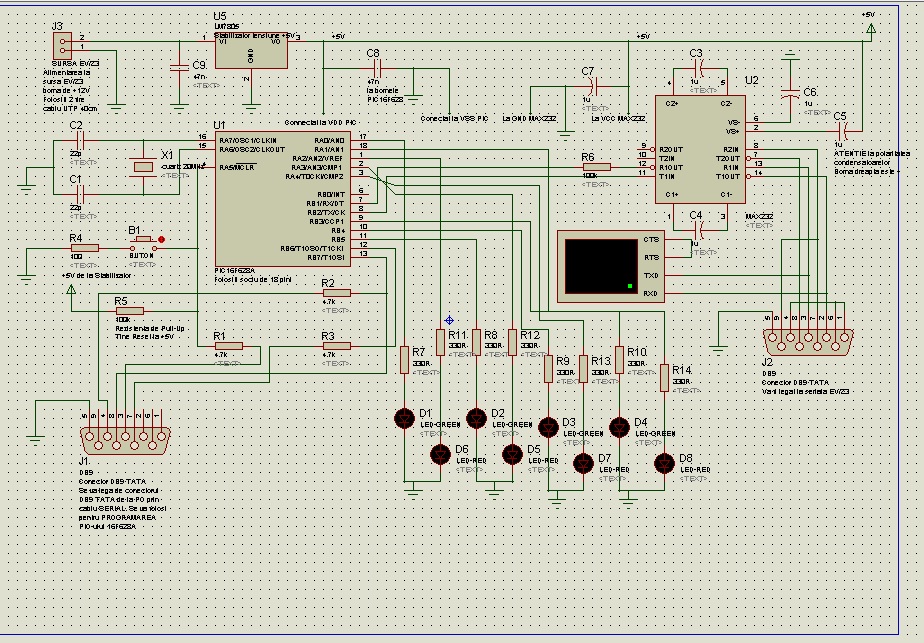
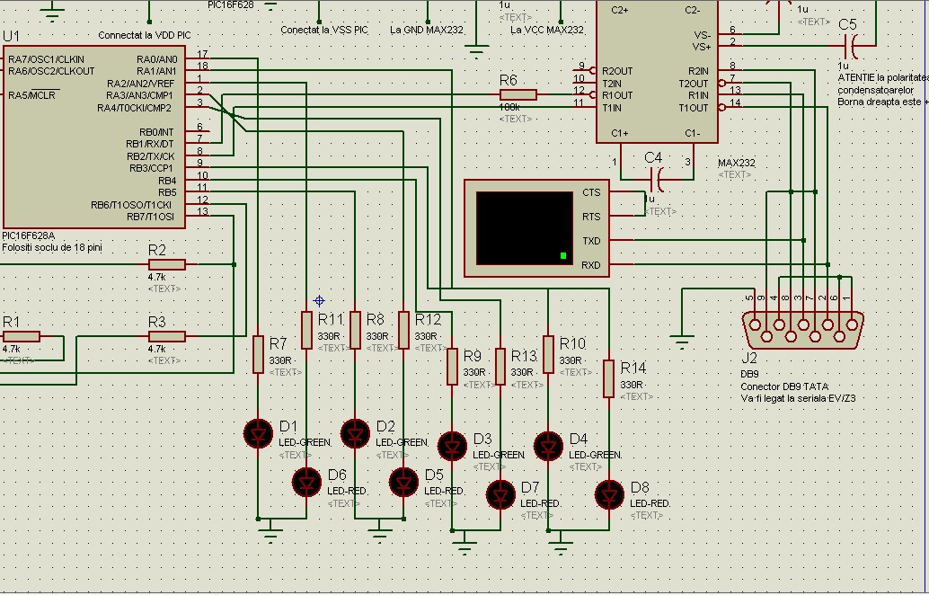
Schema Proteus
Required components
Lista cu componente:
R1-R3 3xrezistente 4,7 kΩ
R4 rezistenta de 100 Ω
R5,R6 2xrezistenta 100 kΩ
R7-R14 8Xrezistenta 330 Ω
4 leduri verzi
4 leduri rosii
C1,C2 2Xcondenstatoare 22pF
C3-C7 5Xcondensatoare 1μF
C8,C9 2Xcondensatoare 47nF
MAX232 + soclu de 16 pini
PIC16F628A + soclu de 18 pini
Stabilizator de tensiune LM7805
Cuartz 20MHz
Buton
2 Conectori DB9 TATA
placa de test
1 letcon 40W-60W
fludor 1-1,5 mm
multimetru
cablu UTP(am folosit firele din cablu pentru conectarea elementelor de pe placa de test).
Software Design
Pentru programarea microcontroller-ului am folosit urmatorul program:
#include <16f628a.h>
#use delay(clock=20M)
#use rs232(UART1,baud=9600, xmit=PIN_B2,rcv=PIN_B1)
void main(){
char *c;
output_low(PIN_A2);
output_low(PIN_A3);
output_low(PIN_A4);
output_low(PIN_A0);
output_low(PIN_B4);
output_low(PIN_B5);
output_low(PIN_A1);
output_low(PIN_B3);
while(1){
c=getc();
if (c==0){ //stare 1
output_low(PIN_B3); // se stinge rosu semafor 1;
output_high(PIN_A1); // se aprinde verde semafor 1;
output_high(PIN_A2); // se aprinde rosu semafor 2;
output_low(PIN_A0); // se stinge verde semafor 2;
output_high(PIN_A3); // se aprinde rosu semafor 3;
output_low(PIN_B5); // se stinge verde semafor 3;
output_high(PIN_A4); // se aprinde rosu semafor 4;
output_low(PIN_B4); // se stinge verde semafor 4;
delay_ms(500);
}
if (c==1){ //stare 2
output_high(PIN_B3); // se aprinde rosu semafor 1;
output_low(PIN_A1); // se stinge verde semafor 1;
output_low(PIN_A2); // se stinge rosu semafor 2;
output_high(PIN_A0); // se aprinde verde semafor 2;
output_high(PIN_A3); // se aprinde rosu semafor 3;
output_low(PIN_B5); // se stinge verde semafor 3;
output_high(PIN_A4); // se aprinde rosu semafor 4;
output_low(PIN_B4); // se stinge verde semafor 4;
delay_ms(500);
}
if (c==2){ //stare 3
output_high(PIN_B3); // se aprinde rosu semafor 1;
output_low(PIN_A1); // se stinge verde semafor 1;
output_high(PIN_A2); // se aprinde rosu semafor 2;
output_low(PIN_A0); // se stinge verde semafor 2;
output_low(PIN_A3); // se stinge rosu semafor 3;
output_high(PIN_B5); // se aprinde verde semafor 3;
output_high(PIN_A4); // se aprinde rosu semafor 4;
output_low(PIN_B4); // se stinge verde semafor 4;
delay_ms(500);
}
if (c==3){ //stare 4
output_high(PIN_B3); // se aprinde rosu semafor 1;
output_low(PIN_A1); // se stinge verde semafor 1;
output_high(PIN_A2); // se aprinde rosu semafor 2;
output_low(PIN_A0); // se stinge verde semafor 2;
output_high(PIN_A3); // se aprinde rosu semafor 3;
output_low(PIN_B5); // se stinge verde semafor 3;
output_low(PIN_A4); // se stinge rosu semafor 4;
output_high(PIN_B4); // se aprinde verde semafor 4;
delay_ms(500);
}
}
}
Codul din programul Open Watcom IDE:
#include "platform_io.h"
const char *welcome = "Semafor ";
int cod;
const char *stare1="stare 1";
const char *stare2="stare 2";
const char *stare3="stare 3";
const char *stare4="stare 4";
int main()
{
int key;
kIo.DisplayString(welcome);
kIo.Wait(1000);
/* Serial Initialization */
serialConf.baudRate = b9600;
serialConf.parity = none;
serialConf.stopBits = one;
serialConf.wordLength = eight;
kIo.SerialInit(&serialConf);
while(1){
key = kIo.ReadKey();
if(key==12){
cod=0;
kIo.SerialWrite(COM1,cod,1);
kIo.DisplayString(stare1);
kIo.Wait(1000);
}
if(key==11){
cod=1;
kIo.SerialWrite(COM1,cod,1);
kIo.DisplayString(stare2);
kIo.Wait(1000);
}
if(key==8){
cod=2;
kIo.SerialWrite(COM1,cod,1);
kIo.DisplayString(stare3);
kIo.Wait(1000);
}
if(key==5){
cod=3;
kIo.SerialWrite(COM1,cod,1);
kIo.DisplayString(stare4);
kIo.Wait(1000);
}
return 0;
}
Results


Download
Arhiva cu schema hardware + cod microcontroller + tot proiectul OpenWatcom.
Arhiva va contine 2 directoare (1 singur pentru proiecte doar software)
Hardware design - schema uC + codul folosit pentru a genera fisierul .HEX
Software design - template-ul Open Watcom folosit
Status
15-17.04.2011 - Documentare proiect
21.04.2011 - Cumparare componente pentru placuta
28,30.04.2011 - Lipire o parte din componente pe placuta
5.05.2011 - Finalizare placuta
10.05.2011 - Probare placuta la laborator, generare cod
19.05.2011 - Prezentare proiect